How to a four way switch wiring
a
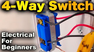
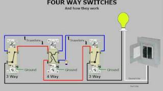
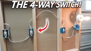
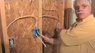
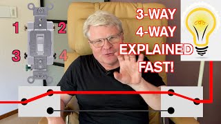
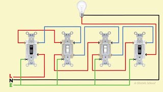
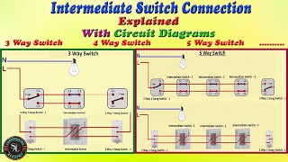
Four Way Switching Explained - How to wire 4 way intermediate light switch
Timecodes:
No transcript (subtitles) available for this video...
Related queries:
how is a four way switch wiring
how to wire a four way switch diagram
how to wire a four way switch circuit
how to wire a four way switch with multiple lights
how to wire a four way switch with one light
how do you wire a 4-way switch
how is a 4 way switch wiring
how to wire three way and four way switches